Bilal Shihab / Projects

ECG PCB

An electrocardiogram board my team designed, built and tested for a BME lab class. It picked up a clean ECG:

Collaborated with Diya Arvindh and Emily NetemeyerBME lab, UT AustinMar – Apr 2025
Specfrom our lab presentation
Amplifier
AD620, RG = 199.74 Ω
Gain
~248 (≈ 48 dB)
High-pass
0.324 Hz (1.49 MΩ, 331 nF)
Low-pass
39.4 Hz (9.93 kΩ, 407 nF)
Output
Voltage follower
Readout
LabVIEW
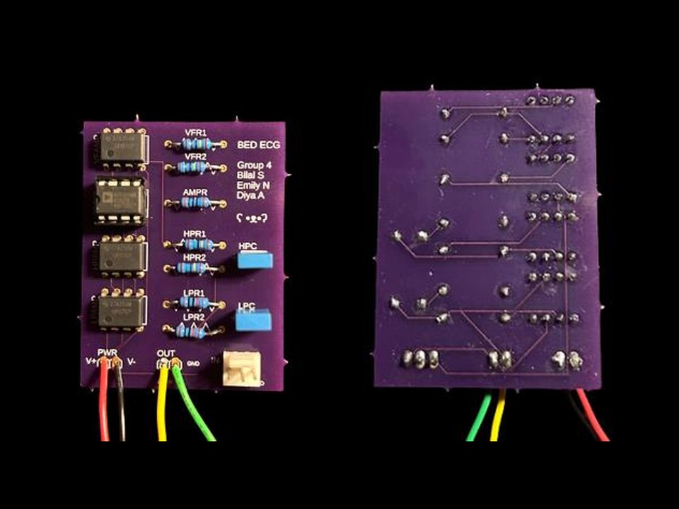
The purple ECG circuit board, front and back
Fig. 1The finished board, front and back.
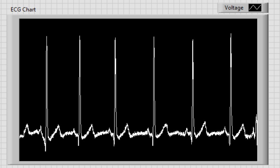
A clean ECG trace in LabVIEW with regular QRS spikes
Fig. 2The board's output in LabVIEW: a clean ECG with regular QRS spikes.
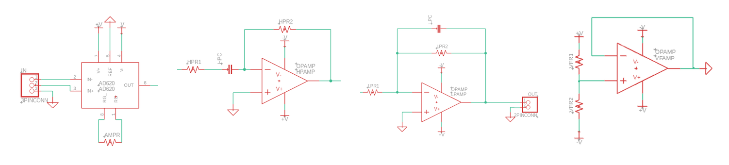
Schematics for the amplifier, high-pass filter, low-pass filter and voltage follower
Fig. 3The four stages in signal order: instrumentation amplifier, high-pass filter, low-pass filter, voltage follower.

Why I built it

It was the design project for a BME lab class: build a circuit that turns the raw heart signal from the skin into a readable ECG.

The hard part

The hardware was the hardest part. Every joint had to be soldered cleanly, and two of the three boards we received had manufacturing defects. Whenever the signal looked wrong, we had to determine whether the cause was our soldering, a defect in the board, or signal acquisition, and we kept iterating until one board produced the clean trace in Fig. 2.